Backup Emergency Signaling (RSA) works independently of the control and supervision system (SSiN) and is used to generate sound, light and other alarms. Alarms are generated as a result of defining logical dependencies and inform employees about events at the power station.
From the hardware side, RSA can be divided into the following blocks:
The above functional blocks are connected with each other by galvanically separated communication interfaces. The entire RSA can be connected to other SAS components via an optical network link. The modules are placed in a 19” cassette with an LVDS type bus.
The BAS Signal Acquisition block may consist of the following types of modules:
The field signaling module (PMS) type SO-52v21-PMS is intended for local collection of signals about the status of devices in the field of a power station or other industrial installation, local presentation of these signals on an integrated presentation panel, creation and presentation of appropriately defined collective signals and sending them to SSiN (Control and Supervision System). These functions are performed autonomously and independently of the signal collection and processing system by SCADA systems.
The above signals are derived directly from station devices or circuits or are the result of defined relationships between the collected signals. The PMS, together with appropriate communication connections, may be part of the reserve emergency signaling system (RSA) functioning in any station automation system.
PMS is designed to work in difficult environmental conditions. It meets the environmental requirements and EMC compatibility requirements specified in the relevant standards for devices and installations operating at the power station. []
SO-52v21-PMS is made as a device consisting of:
BAS is integrated in one housing with PSD. The device can communicate with a remote hub using one or more physical Ethernet interfaces in the 100Base-TX or 100Base-FX standard intended for transmitting data to the remote system, as well as for panel configuration. It is possible to configure VLAN links on installed Ethernet links. The device also has an RS-485 and RS-232 connection for connecting other devices. They can also be used to perform configuration or communication.
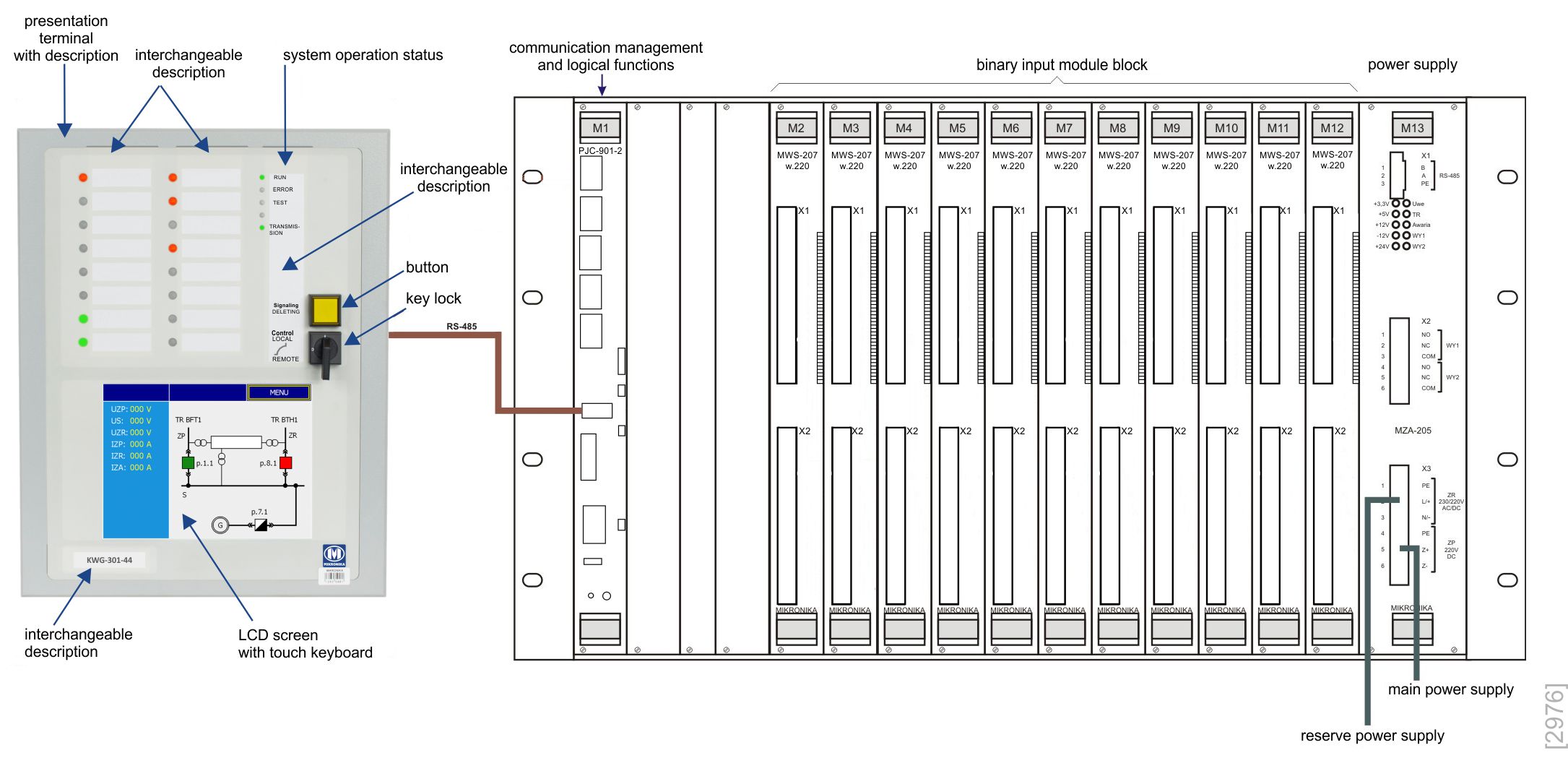
A typical PSD block of the SO-52v21-PMS field signaling module has 72 RGB signaling diodes, 3 additional signaling diodes, 3 buttons and a key switch.
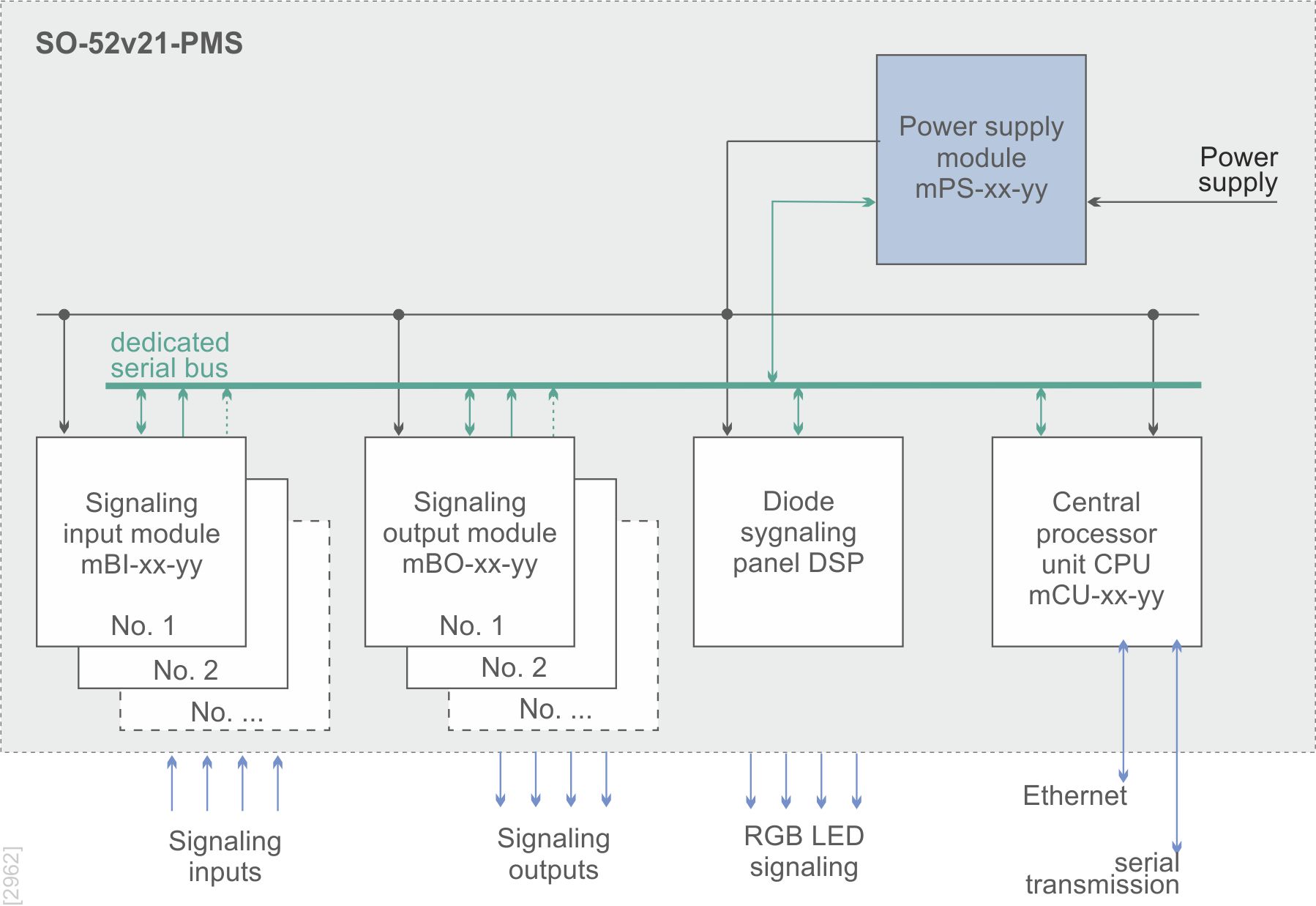
The SO-52v21-PMS block diagram is shown on the right.
BAS is based on specialized cards from the SO-52v21 family. It consists of:
In a typical configuration, the BAS has 4 inputs with a load capacity of 5A/220V or 8 outputs with a load capacity of 0.3A/220V. []
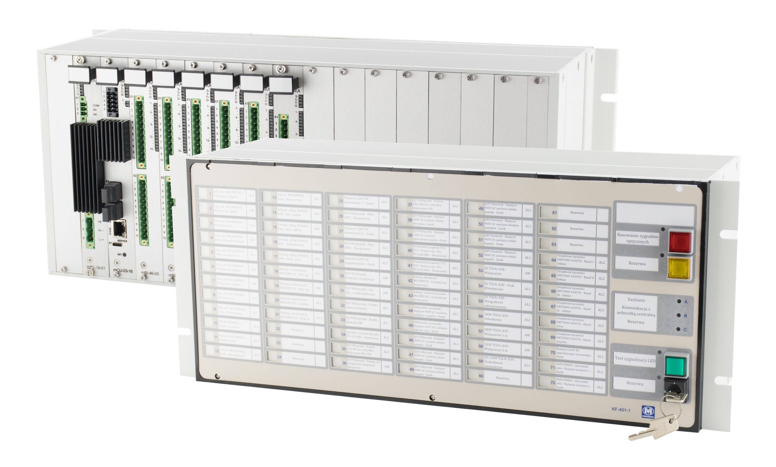
Emergency signaling panels are used to signal the status of warning and alarm signals in a power station or other industrial installation, independently and autonomously from the SCADA signal collection and processing system.
The above signals are introduced directly from devices or station circuits or are the result of defined relationships between the collected signals. The described equipment from the SO-52PSC-500-xxxx family, together with software and communication solutions, can be included in the reserve emergency signaling system (RSA), functioning in any station automation system.
The SO-52PSC-500-xxxx series devices are designed to operate in difficult environmental conditions. They meet the environmental requirements and EMC compatibility requirements specified in the relevant standards for devices and installations operating at the power station. []
SO-52PCS-500-xxxx is available in two structural and functional variants: MASTER and EXTENSION.
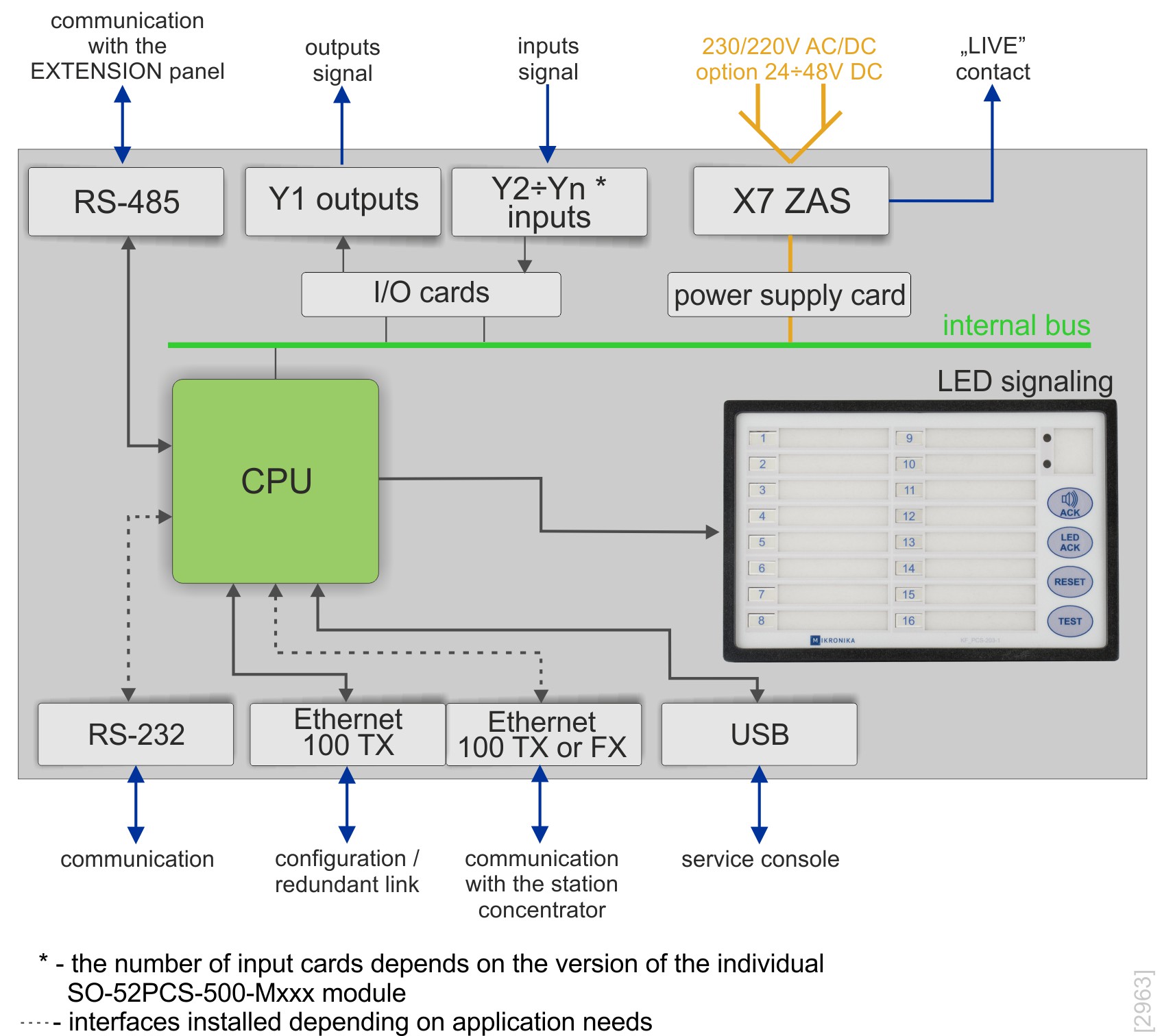
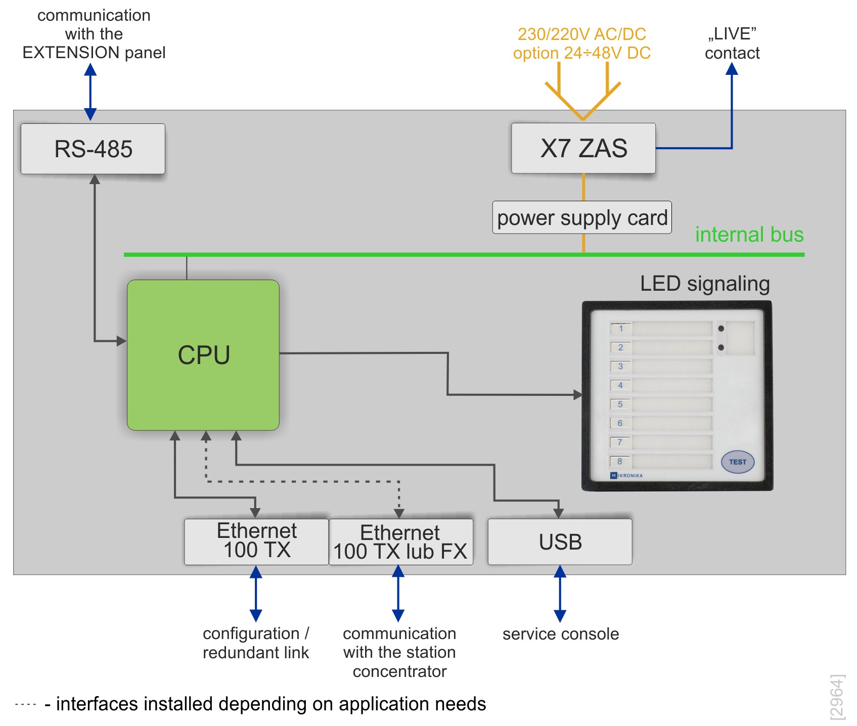
The SO-52PCS-500-Mxxx variant, the so-called MASTER consists of a Signal Acquisition Block (BAS) and a Diode Signaling Panel (PCS). BAS is integrated in one housing with PCS. MASTER panels can communicate with the concentrator using one or two physical Ethernet interfaces in the 100Base-TX or 100Base-FX standard. In addition, MASTER panels have an RS-485 connection for possible connection of EXTENSION type expansion panels. The block diagram of this variant is shown in the figure below.
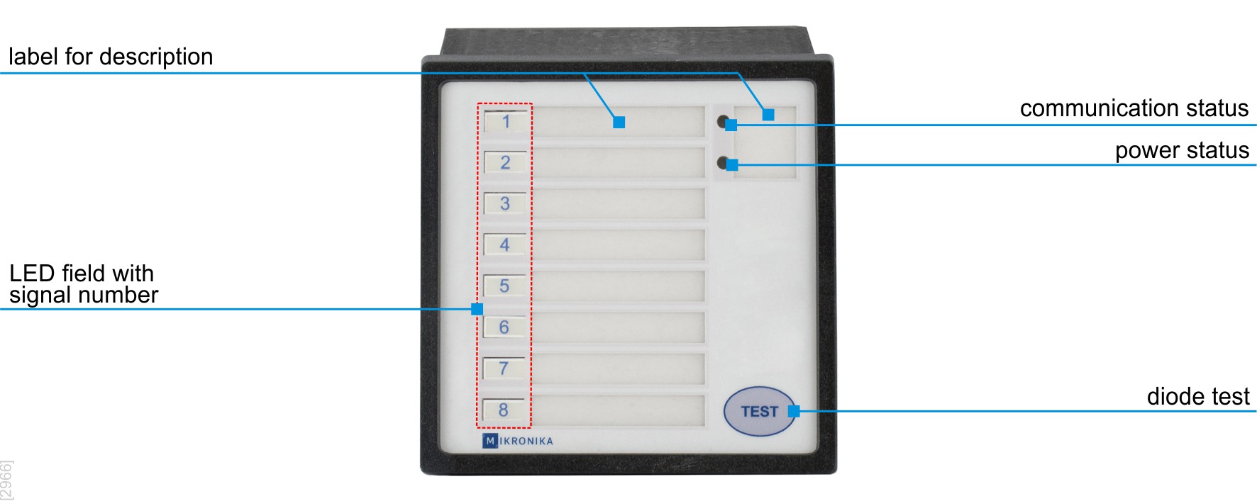
The SO-52PCS-500-Exxx variant, the so-called EXTENSION does not have input signal interfaces within BAS. It may have network communication channels, including the possibility of configuring VLAN channels. The EXTENSION module is used in applications where it is necessary to expand the number of LED signaling while maintaining the number of input signals installed in the SO-52PCS-500-Mxxx variant. EXTENSION panels can communicate with the MASTER panel via an RS-485 link. These panels can also be used in applications where it is required to separate the module collecting input signals from the presentation modules. The block diagram of this variant is shown next to it, below.
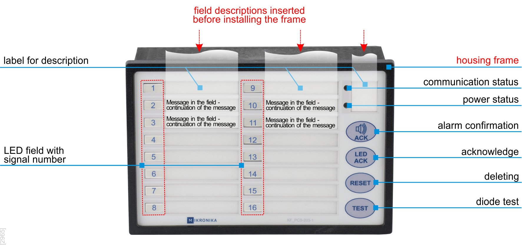
Both variants have an internal communication bus, allowing the expansion of inputs and outputs by installing an appropriate card. Each variant has several versions depending on the number of required LED signals, input signals and communication channels. The PCS visualization panel consists of 8, 16, 24, 32, 40 or 48 RGB LEDs with adjustable brightness. They are placed on the front panel of the SO-52PCS-500-xxxx, in the housing in which the BAS is installed. The MASTER variant also includes functional buttons for acknowledging alarms, initiating an internal test and restarting the panel. The EXTENSION variant only contains a testing button. []
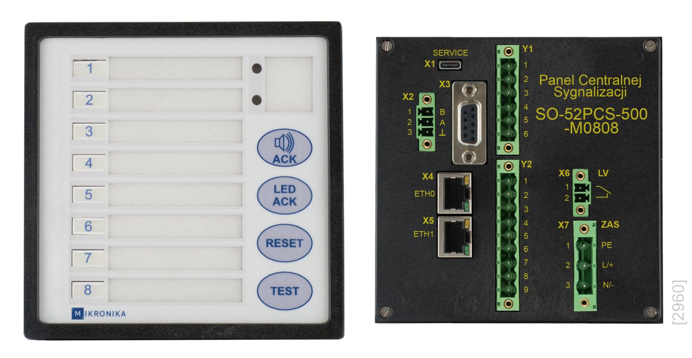
The MASTER variant panel containing 8 RGB LEDs, 8 binary inputs for 220V DC and 3 control outputs and communication channels is named SO-52PCS-500-M0808-x-x. **)
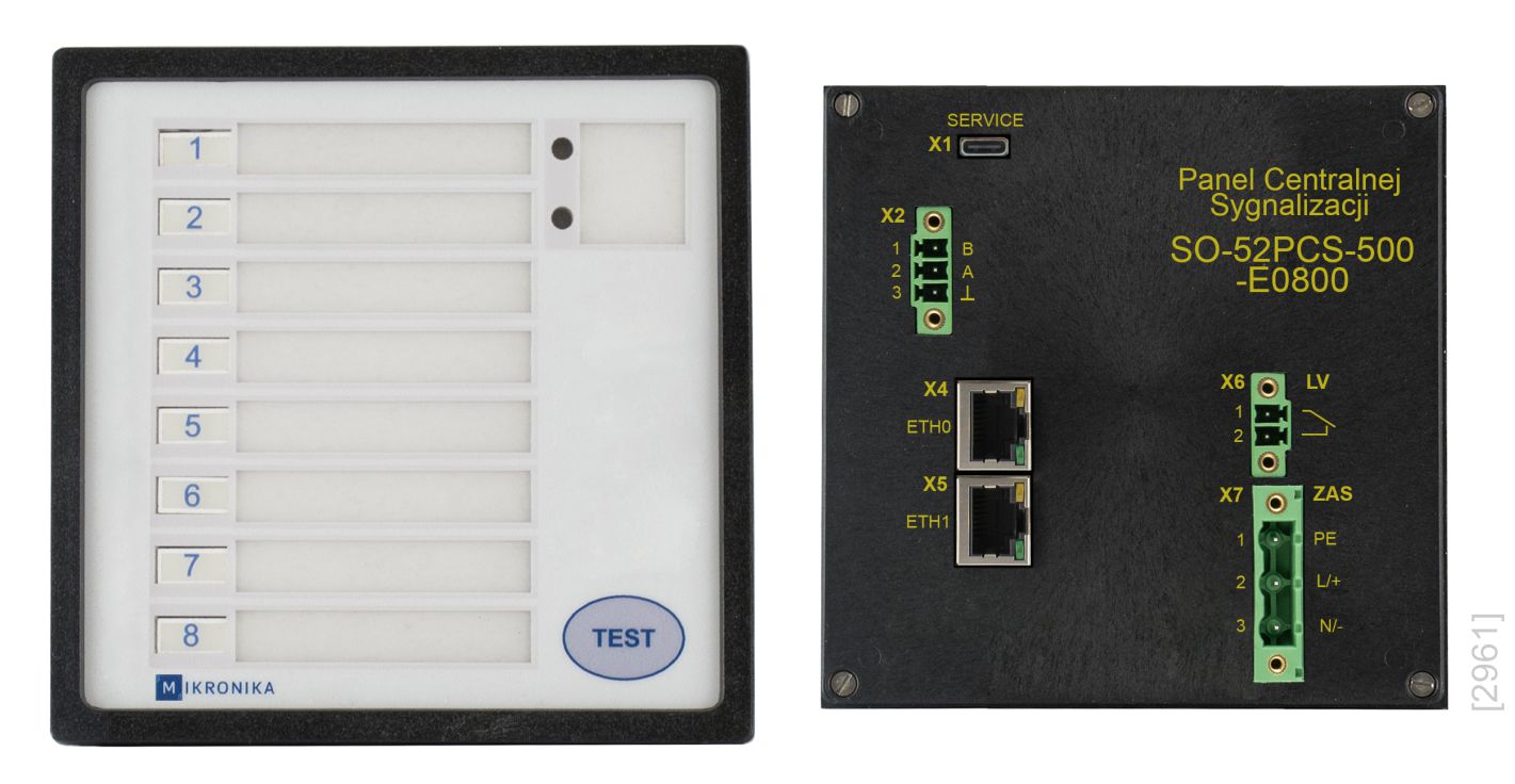
The EXTENSION panel with 8 RGB LEDs and communication channels is named SO-52PCS-500-E0800-x. **)
In a typical configuration, the BAS has 4 inputs with a load capacity of 5A/220V or 8 outputs with a load capacity of 0.3A/220V. []