COLOR - not recommended for use | COLOR - module/device manufactured
[replaced by SO-52v11-S-2]
The SO-52v11-S synchronizer is a specialized device designed to control and monitor the process of connecting two power lines. Its task is to protect the circuit breaker against the flow of inadmissible current at the time of switching.
The SO-52v11-S synchronizer is designed to perform the function of synchronous switching on of circuit breakers in power switchgear bays of all voltage types. The device controls a circuit breaker synchronized to a bus or bay reference voltage. At the power station, the device can function in a central synchronization system or as a field synchronizer. Implemented, standardized communication protocols allow for full cooperation with superior systems of various manufacturers. The product is intended for applications in difficult environmental conditions, in the presence of high dust, moisture and electromagnetic interference. []
[replaced by SO-52v11-S-2]
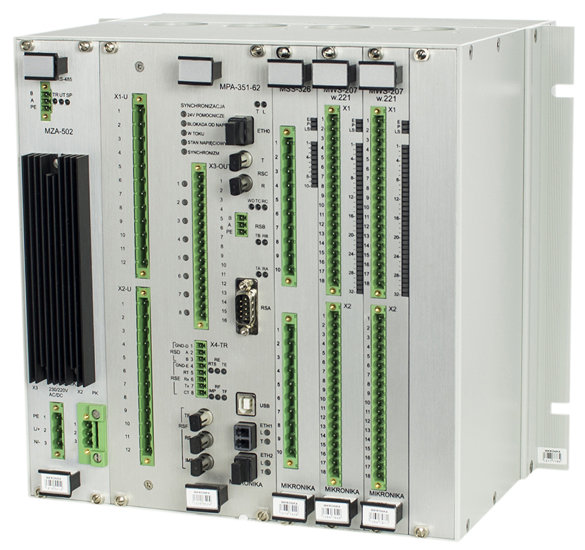
The SO-52v11-S-1 circuit breaker synchronism controller is designed to perform the function of synchronous switching of circuit breakers in power switchgear bays of all voltage types. The device controls the circuit breaker with synchronization to the bus reference voltage. At the power substation, the device can function in a central synchronization system or as a field synchronizer.
The circuit breaker synchronism controller is made as a set of modules placed in a closed 10”/6U type housing. Depending on the field type, the number of binary input/output modules may be different. The minimum configuration has one MWS input packet and one MSS output packet.
The following types of modules can be placed in the housing:
The measurement and communication module performs measurements, calculations, necessary control algorithms, internal communication with other synchronizer modules and the required external communication. The transmission links of the module enable the creation of redundant communication with the device.
The controller can be equipped with a graphic terminal and additional binary input or output packages. []
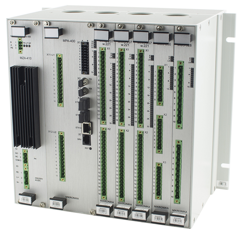
The SO-52v11-S-2 circuit breaker synchronism controller is designed to implement the function of synchronous switching of circuit breakers in power distribution bays of all voltage types. The device controls the circuit breaker with synchronization in relation to the reference voltage of the bus. In the power station, the device can operate in a central synchronization system or as a bay synchronizer.
The circuit breaker synchronism controller is made as a set of modules placed in a closed 10”/6U housing. Depending on the type of bay, the number of binary input/output modules may be different. In the minimum configuration, there is one MWS input package and one MSS output package.
The following types of modules can be placed in the housing:
The measurement module performs measurements, calculations, necessary control algorithms, and the MPA module provides internal communication with other synchronizer modules and required external communication. The module's transmission links enable the creation of redundant communication with the device.
The binary input modules perform the acquisition of binary signals from the object. They cooperate with other modules via the internal bus. The control input modules perform the required controls in the synchronizer system. Depending on the version, the modules are adapted to perform high-current 5A/220V DC and low-current 0.25A/220V DC controls. The controller can be equipped with a graphic terminal and additional binary input or output packages.
The block diagram of the SO-52v11-S-2 circuit breaker synchronism controller is shown below.
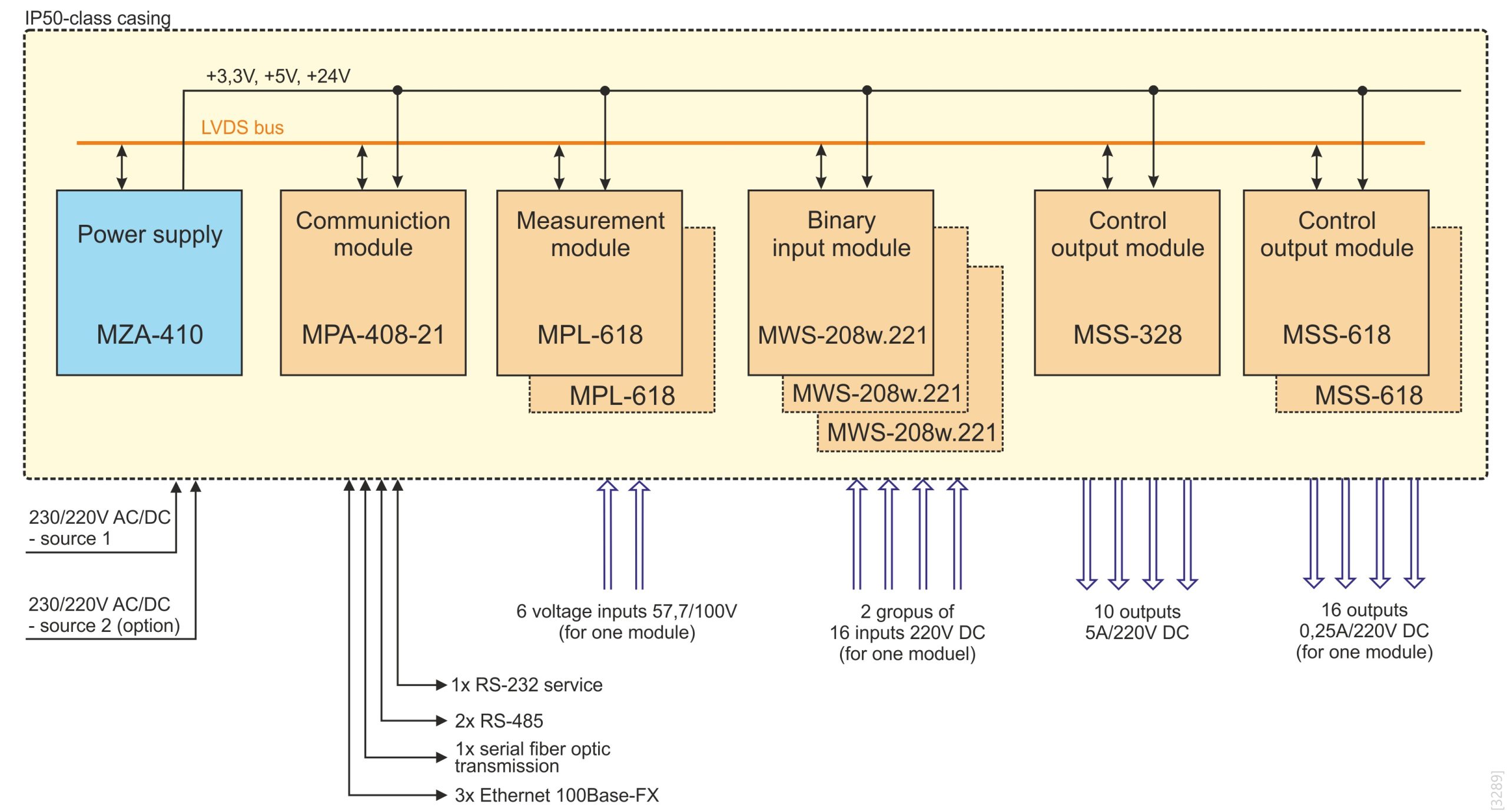
The synchronizer can be used as a field or central. The device has a modular design that allows for its expansion. []
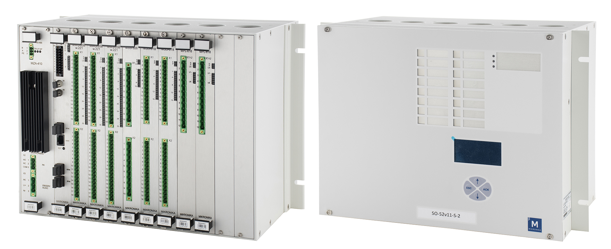
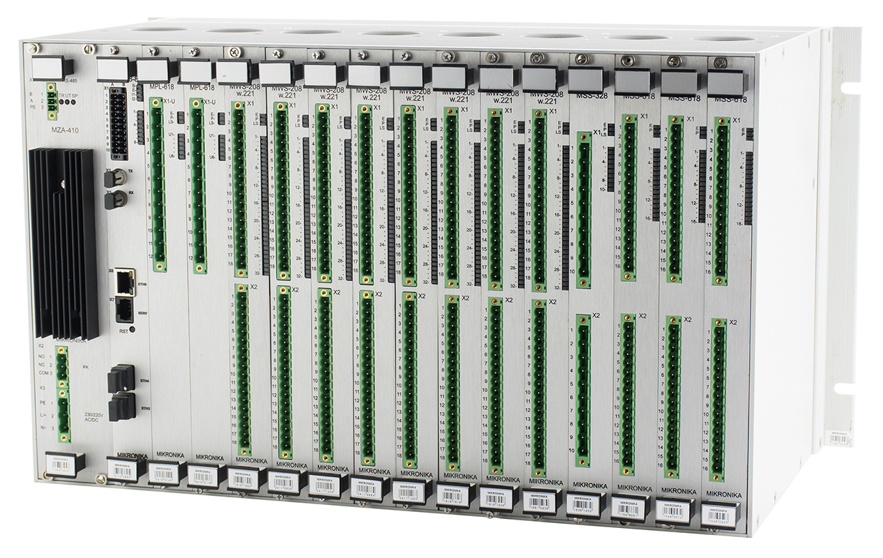
The SO-52v11-S-3 controller is recommended as a central synchronism controller supporting multiple bays (breakers). The SO-52v11-S-3 breaker synchronism controller is a more advanced version of the SO-52v11-S-2 controller. The …-S-3 device can support up to 8 binary input packages MWS and 4 binary output packages MSS. An example configuration with a full set of packages is shown below. []
In addition, the controller has measurement and communication modules (MPA and MPL), which perform measurements, calculations and network or serial transmission with external communication controllers or other systems. The transmission links of the communication module enable the creation of redundant communication with the device.
Control output modules perform the necessary controls required in the synchronizer system. Depending on the type of modules used, high-current 5A/220V DC or low-current 0.25A/220V DC controls can be performed. []
The whole package is completed by a high-performance MZA power supply, which provides the necessary voltages for the correct operation of the controller. All breaker synchronism controller modules are powered by the internal bus.
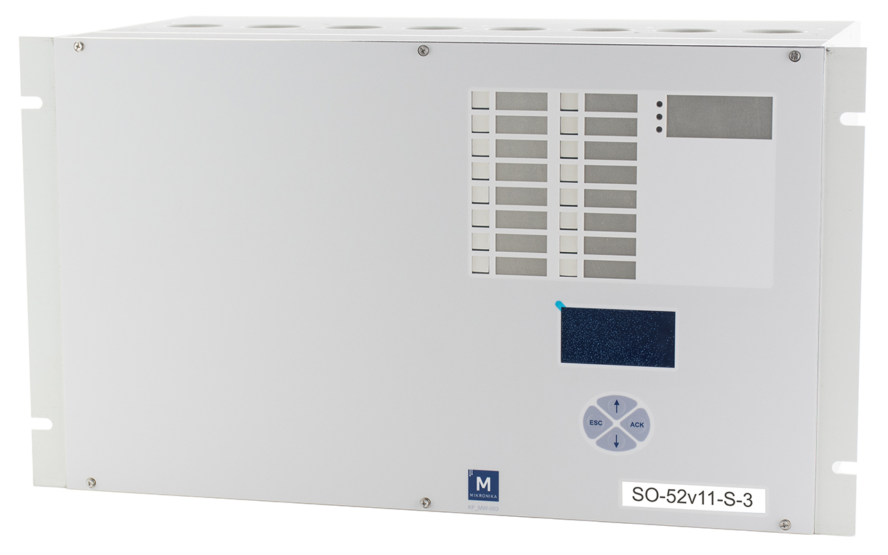
The device can be additionally equipped with a graphic terminal placed on the front of the device. It is used to display the basic operating parameters of the device. The user interface consists of a monochrome LCD display, four control buttons and sixteen signaling diodes. The diode signaling can refer to any signals that are assigned during configuration. The diodes can operate in signaling or alarm mode. The data presented on the display can be of both informational and warning nature. Any data and operating states of the breaker synchronization controller can be represented. The controller is shown next to it from the graphic console side. []
[replaced by SO-52v11-S-2]
The SO-5431 synchronizer is designed to control and monitor the process of connecting two power lines.
Parameters that are subject to control:
Based on the controlled parameters, the device gives a signal of readiness to connect both lines. The main task of the system is to generate a closing impulse for the circuit breaker when the defined amplitude, frequency and phase conditions of both measured voltages are met. alternating variables that uniquely identify the synchronism of the network.
These conditions are defined as follows:
Permission to close the circuit breaker is generated only when all conditions are met simultaneously. []