These devices are adapted for communication with many devices that do not require simultaneous operation. These devices work in address or unaddressed mode.
COLOR - not recommended for use | COLOR - module/device manufactured
The task of the MKT-130 is to transmit binary data in eight channels, in the transmitting and receiving paths, using a pair of optical fibers that make up the collective transmission channel. The device has been designed for transmission systems where data transmission is limited. The device has the option of duplicating the collective channel. Then, of course, an additional pair of optical fibers is required, creating a duplicate transmission channel.
The communication elements are completely separated from the rest of the system. The RS-232 service interface is also separated. Galvanic isolation protects the device against overvoltages that may occur on transmission lines.
The RS-232 service link is intended for configuration and firmware uploading. The duplicator is equipped with an AC / DC power supply. As standard, the housing is adapted to mounting on a 35 mm DIN rail, but it is also possible to mount a 19" panel or a specialized one. []
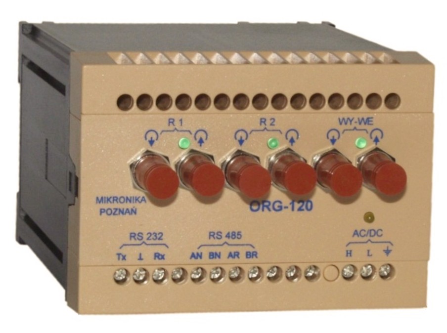
ORG-xxx data multiplexers are designed to implement two ring networks of connections between devices equipped with an optical interface, RS-232 or
RS-485, two- or four-wire.
ORG-xxx enables the device to be connected to two networks, which allows for the implementation of e.g. redundant communication, communication with two independent dispatch centers or the implementation of remote communication and local monitoring.
Communication with the ORG-xxx device takes place in the half-duplex mode. Only one of the devices that are connected can transmit data at a time. The device has an integrated power supply and can be supplied with 110-220V AC/DC or 24-48V AC/DC. The multiplexer provides galvanic separation of RS-232 or
RS-485 links from the supply voltage. The ORG-xxx device is manufactured in an enclosure that enables mounting on a 35 mm DIN rail. []
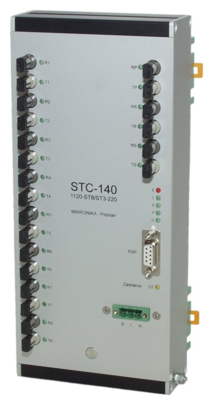
STC Transmission Multiplexers are designed for systems where there is a need to communicate with multiple slave devices operated by one or two master channels. One of these channels is the primary channel and the other is the backup channel. STC devices can work in several modes of the standard serial transmission multiplexer, as well as in more advanced modes, allowing for control and supervision of the transmission.
These devices can have a built-in 100MB Ethernet interface in a twisted-pair or fiber-optic standard. The use of a network link makes it possible to combine into one, extensive system of very diverse devices, e.g. security, recorders, object controllers. []
Not recommended for apply in new solutions
The STC-2xx family of devices can be divided into two functional groups.
The first group. It consists of devices for remote access to many slave devices (e.g. security devices, disturbance recorders, data concentrators) with the use of one master link. The STC-2xx enables the establishment of a "transparent connection" between one slave device and a remote master system. The master channel can be made by multimode fiber, PSTN modem or GSM / CSD modem. The slave interfaces are also made as RS-232, RS-485, single- or multi-mode optical fibers.
The second group is the logically inverted first group. It consists of devices that perform the function of a transmission multiplexer. In this case, there is a need to communicate with multiple slaves using one or two master channels. In such systems, apart from the functions of splitting and summing transmission signals, there is a need to duplicate the master channels in order to increase the security of transmission. The master channel can be made in fiber optic technology, single- or multimode, glass or plastic, or in the form of an RS-485 interface. Slave interfaces can be made as RS-485, single- or multi-mode optical fibers (glass or plastic).
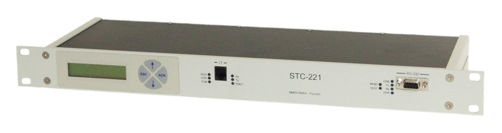
At the rear of the device, 11 connectors are led out, which, depending on the prepared device configuration, are as follows:
On the front panel of the device, there are also connectors: RS-232 (service - for configuration, status viewing, etc.), RJ-12 (telephone line connection), SMA (socket for GPS antenna connection), as well as a display and a keyboard.
STC-2xx is made in a 1U housing, designed for installation in a 19” rack. []
Not recommended for apply in new solutions
The STC-3xx switch has been developed for systems where it is necessary to communicate with multiple slave devices via Ethernet. The device allows you to establish a network connection between one of the slave devices and a remote master system within the so-called remote engineering link. The switch ensures correct cooperation with various types of slave devices for the purpose of their parameterization, data reading and operation control.
The STC-3xx switch is equipped with 11 transmission channels. After establishing the connection with the network port (TCP / UDP), the transmission takes place from the network port to the serial port and vice versa, which means that devices connected to the serial ports will be visible in the Ethernet network.
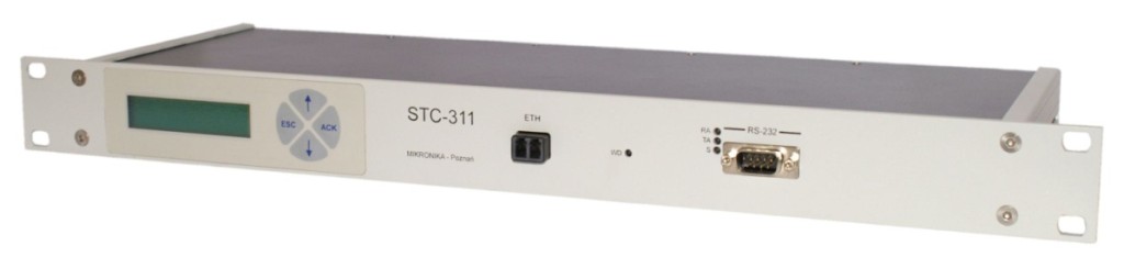
At the rear of the device, 11 connectors are led out, which, depending on the prepared device configuration, are as follows:
On the front panel of the device, there are also connectors: RS-232 (service - for configuration, status viewing, etc.), RJ-45 (for connecting the Ethernet network), as well as a display and a keyboard.
The STC-3xx switch is made in a 1U casing, designed for installation in a 19” rack. []
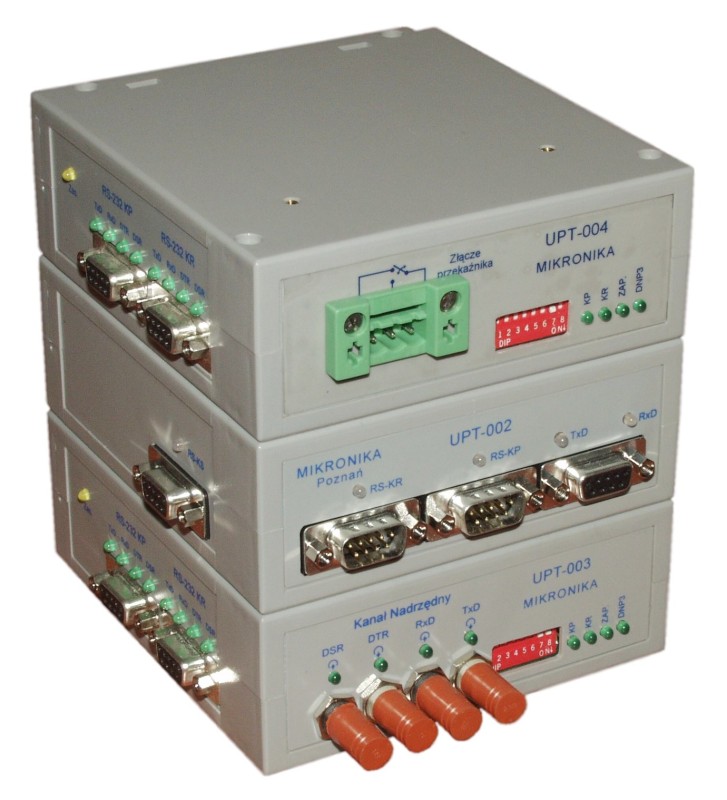
The UPT-00x system provides switching of transmission paths. It was designed for systems with double RS-232 links, one of which is the so-called primary channel and backup second channel. The device allows you to control data transmission and control their flow in the primary or backup channel, depending on the state of the links.
The system can control the transmission in two ways. First variant: data is permanently switched to the first (primary) or second (backup) channel. The second variant: the system works in the self-supervision mode, independently controlling the transmission depending on the state of the links.
Each device consists of four channels: two RS-232 channels (primary and backup), RS-232 control (service) channel and main (RS-232 or fiber optic) channel.
All transmission channels (including service channels) are galvanically isolated from other parts of the switch. Galvanic isolation protects the device against overvoltages that may occur on transmission lines. The device has a housing that can be mounted on a 35 mm DIN rail. []
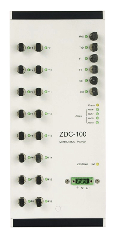
The ZDC-100 Managed Frequency Divider is used to divide and distribute the clock signal with multimode optical fibers.
Each ZDC-100 has:
A channel is a transmitter and receiver unit that enables independent transmission in both directions. []